Download Tutorial Lengkap (PDF 291 KB)
AERODYNAMICS FORCES ON WING
2.1 Angle of Attack
The above phenomena is happened when aircraft wing is inline with wind direction. What if there is an angle between aircraft wing and wind direction. This angle is usually called angle of attack.
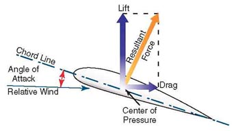
The angle of attack is the angle between an airfoil and the oncoming air. A symmetrical airfoil will generate zero lift at zero angle of attack. But as the angle of attack increases, the air is deflected through a larger angle and the vertical component of the airstream velocity increases, resulting in more lift. For small angles a symmetrical airfoil will generate a lift force roughly proportional to the angle of attack.

As the angle of attack grows larger, the lift reaches a maximum at some angle; increasing the angle of attack beyond this critical angle of attack causes the air to become turbulent and separate from the wing; there is less deflection downward so the airfoil generates less lift. The airfoil is said to be stalled.
Cambered airfoils will generate lift at zero angle of attack. When the chordline is horizontal, the trailing edge has a downward direction and since the air follows the trailing edge it is deflected downward. When a cambered airfoil is upside down, the angle of attack can be adjusted so that the lift force is upwards. This explains how a plane can fly upside down.
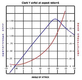
2.2 Lift & Drag Coefficient
Lift Force and Drag Force of each airfoil may be figured out as curvas. This curva is know as Lift Coeffisient and Drag Coffensient of the airfoil for each angle of attack.
2.3 Pressure Distribution
From experiments conducted on wind tunnel models and on full size airplanes, it has been determined that as air flows along the surface of a wing at different angles of attack, there are regions along the surface where the pressure is negative, or less than atmospheric, and regions where the pressure is positive, or greater than atmospheric. This negative pressure on the upper surface creates a relatively larger force on the wing than is caused by the positive pressure resulting from the air striking the lower wing surface.
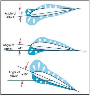
Figure above shows the pressure distribution along an airfoil at three different angles of attack. In general, at high angles of attack the center of pressure moves forward, while at low angles of attack the center of pressure moves aft. In the design of wing structures, this center of pressure travel is very important, since it affects the position of the airloads imposed on the wing structure in low angle-of-attack conditions and high angle-of-attack conditions. The airplane’s aerodynamic balance and controllability are governed by changes in the center of pressure.
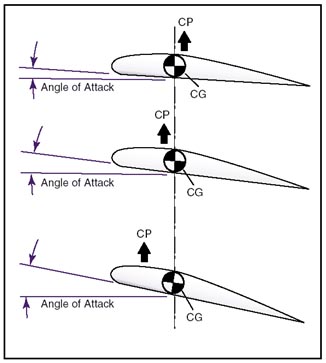
2.4 Center of Gravity (CG) vs. Center or Pressure (CP)
The center of pressure is determined through calculation and wind tunnel tests by varying the airfoil’s angle of attack through normal operating extremes. As the angle of attack is changed, so are the various pressure distribution characteristics.
Positive (+) and negative (–) pressure forces are totaled for each angle of attack and the resultant force is obtained. The total resultant pressure is represented by the resultant force vector shown in figure above.
The point of application of this force vector is termed the "center of pressure" (CP). For any given angle of attack, the center of pressure is the point where the resultant force crosses the chord line. This point is expressed as a percentage of the chord of the airfoil.
A center of pressure at 30 percent of a 60-inch chord would be 18 inches aft of the wing’s leading edge. It would appear then that if the designer would place the wing so that its center of pressure was at the airplane’s center of gravity, the airplane would always balance. The difficulty arises, however, that the location of the center of pressure changes with change in the airfoil’s angle of attack.
In the airplane’s normal range of flight attitudes, if the angle of attack is increased, the center of pressure moves forward; and if decreased, it moves rearward. Since the center of gravity is fixed at one point, it is evident that as the angle of attack increases, the center of lift (CL) moves ahead of the center of gravity, creating a force which tends to raise the nose of the airplane or tends to increase the angle of attack still more. On the other hand, if the angle of attack is decreased, the center of lift (CL) moves aft and tends to decrease the angle a greater amount. It is seen then, that the ordinary airfoil is inherently unstable, and that an auxiliary device, such as the horizontal tail surface, must be added to make the airplane balance longitudinally.
The balance of an airplane in flight depends, therefore, on the relative position of the center of gravity (CG) and the center of pressure (CP) of the airfoil. Experience has shown that an airplane with the center of gravity in the vicinity of 20 percent of the wing chord can be made to balance and fly satisfactorily.
Airplane loading and weight distribution also affect center of gravity and cause additional forces, which in turn affect airplane balance.
2.5 Aspect Ratio
Aspect ratio is the wing span divided by the mean wing chord. An aircraft with a rectangular wing of area 12 m2 might have a wing span of 8 m and constant wing chord of 1.5 m. In this case the aspect ratio is 5.33. If the span was 12 m and the chord 1 m, then the aspect ratio would be 12. However because wings have varied plan forms, it is usual to express aspect ratio as:
Aspect ratio = wing span2 / wing area
It is conventional to use the symbol "b" to represent span, so the equation above is written as:
A = b2 / S
The Jabirus aspect ratio (span 7.9 m, area 8.0 m2) = 7.9 × 7.9 / 8 = 7.8, whereas an aircraft like the Thruster would have an aspect ratio around 6. Consequently you would expect such an aircraft to induce much more drag at high angles of attack, and thus slow much more rapidly than the Jabiru.
And incidently, the mean chord (not the mean aerodynamic chord) of a wing is span/aspect ratio. A high-performance sailplane wing designed for minimum induced drag over the CL range might have a wingspan of 22 m and an aspect ratio of 30, thus a mean chord of 0.7 m. There are a few ultralight aeroplanes, designed to have reasonable soaring capability, that have aspect ratios around 16–18, but most ultralights would have an aspect ratio between 5.5 and 8, and averaging 6.5. General aviation aircraft have an aspect ratio between 7 and 9, probably averaging around 7.5. Note that the higher the aspect ratio in powered aircraft, the more likely is wingtip damage on landing.
Selamat Terbang...