Date Created: 01-Jun-2013 Created By: Budi Atmoko Category: Aerodynamics
How Aircraft Can Fly
Basic theory of How the air move and push the aircraft to fly
Founded by Daniel Bernoulli
Aircraft can fly phenomena is founded three centuries ago, Daniel Bernoulli, a Swiss mathematician, explained how the pressure of a moving fluid (liquid or gas) varies with its speed of motion. Specifically, he stated that an increase in the speed of movement or flow would cause a decrease in the fluid’s pressure. This is exactly what happens to air passing over the curved top of the airplane wing.
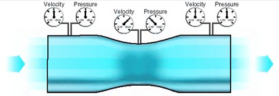
A practical application of Bernoulli’s theorem is the venturi tube. The venturi tube has an air inlet which narrows to a throat (constricted point) and an outlet section which increases in diameter toward the rear. The diameter of the outlet is the same as that of the inlet. At the throat, the airflow speeds up and the pressure decreases; at the outlet, the airflow slows and the pressure increases.
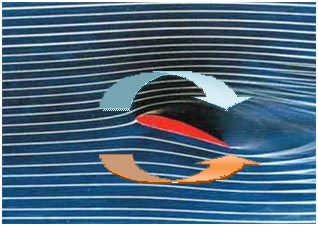
If air flow is moving through an aircraft wing with a specific form, thickness, and angle the air flow a part will be deflected over the wing which has higher air flow speed and air pressure will drecreased and other part is deflected under the aircraft wing which has slower air flow speed and higher air pressure.
Lift Force
The Pressure difference between air flow part deflected under aircraft wing and air flow part deflected over the aircraft wing will create an air pressure force with a direction from under aircraft wing to top aircraft wing. This air pressure force is known also as Lift Force
If air flow is moving through an aircraft wing, it will create a certain Lift Force with perpendicular direction to the air flow. Base on the above phenomena, If an aircraft wing is moved through air with a certain speed, aircraft will have a Lift Force on it’s wing. The faster aircraft moved, the greater Lift Force created. If Lift Force created at aircraft wing is greater than aircraft weight, then aircraft will be forced to fly.
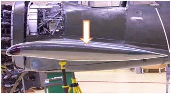
Airfoil
The Bernoulli phenomena is working on the specific form of the aircraft wing. The aircraft wing is not a common form. Not just a flat or thick form but have a specific form. This form (ussually called airfoil), has nearly flat at the bottom and thick at the top of the wing. According The Bernoulli rule, if air flowing to this airfoil, there will be a different air speed between air flowing under the wing and air flow over the airfoil. This air flow speed differences will create Pressure and Lift Force at the aircraft wing. A certain thick size at the top side of the wing is design to create a specified Lift Force required (with a certain air flow speed) by the aircraft, to fly and also movement of the aircraft.
It should be understood that different airfoils have different flight characteristics. Many thousands of airfoils have been tested in wind tunnels and in actual flight, but no one airfoil has been found that satisfies every flight requirement. The weight, speed, and purpose of each airplane dictate the shape of its airfoil. It was learned many years ago that the most efficient airfoil for producing the greatest lift was one that had a concave, or “scooped out” lower surface. Later it was also learned that as a fixed design, this type of airfoil sacrificed too much speed while producing lift and, therefore, was not suitable for high-speed flight. It is interesting to note, however, that through advanced progress in engineering, today’s high-speed jets can again take advantage of the concave airfoil’s high lift characteristics. Leading edge (Kreuger) flaps and trailing edge (Fowler) flaps, when extended from the basic wing structure, literally change the airfoil shape into the classic concave form, thereby generating much greater lift during slow flight conditions.